Selecting the location and mounting the Energy Manager
C.T wiring, P.T wiring, Auxiliary supply and Control Relay wiring
Calibration, Maintenance and field service
Programming of various parameters
CAUTION (Danger)
During normal operation of this energy manager, dangerous voltages are present at the rear of this instrument, on terminals which may cause severe injury or death. these voltages are present on all current transformer, potential transformer auxiliary supply and on control relay terminals of this energy manager. the installation maintenance and service should be carried out by qualified person properly trained for the purpose
The cover of the energy manager should never be opened. there are not any user's serviceable parts inside the energy manager. it contains high precision components to be handled only at sigma's authorized service station or at sigma factory.
Wrong installation, including wrong wiring or improper grounding will void sigma warranty. opening the cover or any attempts to dismantle, service, repair or modify the instrument by un-authorise persons may cause sever demage to the energy manager and void. warranty from sigma
LOCATION
First decide on how Energy Manager is to be used. If you had no prior experience in this regard then you are advised to take advice of an electrical consultant or Sigma's authorized Engineer. This will help you to decide that which load is to be sheded and their priority. Always try to choose the location which provides all required signals and should have minimum wiring.
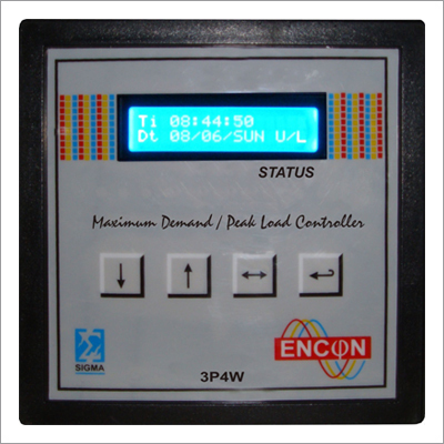
The energy manager has Two Relays out-put as RL-1, RL-2, with common point connected to supply internally. RL_1 operates at 95% of set Maximum demand/Peak Load setting.RL_2 operates at 100% of set value of max_demand/Peak load allowed during this period.
The Energy Manger is a high precision instrument and so its operating atmosphere is very important. For best performance , the energy manager should be mounted in a dry, dust free location, away from heat sources and strong electromagnetic forces. For best performance following conditions must be met.
Strong temperature: Up 70 C.
Operating Temp: 0-50 C .
Relative Humidity: 5-95% non condensing
The energy Manager should be separated from other instrument and sufficient space must be provided all around for cooling air to rise vertically past the instrument. The cooling air temperature must be below the specified operating temperature. The pannel of which the energy is mounted must protect it from dust moisture, oil and water etc.
The panel door must be easily opened easy access to the instrument for wiring or for trouble shooting. Allow clearance if the unit is going to swing out, as well as adequate slack in the wiring. Allow space for terminal blocks and auxiliary contractor and other components.
Viewing
For ease of operation, the location should be preferably at, or slightly above the eye level. For viewing comfort, minimize glare and reflections from straight light sources.
MOUNTING
Before mounting and wiring, following dimension should be followed
Panel cutout: 138 X 138 MM
Front Brazel: 144 X 144 MM
Depth: 120 mm without terminal strip
Mounting Clamp: 2 No for left and right side
WIRING
The measurement accuracy of the energy manager is determined by the accuracy and phase shift of Pt's. The class 1 or off better PT and CT are recommended for use with for use with energy manager. Never use protection class CT's to feed energy manager as the have poor accuracy and phase characteristics.
Be sure that the primary rating of CT's has been selected so that your normal load variation lies between 40 to 80% of full scale. In case you use over rated CT and for i.e 3% to 10% of full load is utilized, the accuracy suffers. And on the other side if you use under-rating CT's it will burn CT's and the energy manager.
PT and CT must have adequate VA rating to bear the burden of the secondaries. In class you want to put the burden of auxiliary supply on PT then this VA rating must be kept in mind more over this situation should be avoided. CT wiring can impose additional loading on CT's. For example, the CT has the 5 Amp. Secondary and the wire resistance is one ohm then the CT has to support 5VA additional burden. So -/5 Amp. CT of 15VA capacity is recommended for use with energy manager. Also it is recommended to use minimum length of CT wire for better results.
NOTE: The Ct's of energy manager is field programmable and any value of CT ranging from 10/5 A to 5000/5A can be entered as detailed in programming. Up to 99.9 the Ampere parameters are displayed with one decimal point and without decimal for values 100 Amp
EARTH CONNECTION
For the best grounding, use a dedicated solid copper wire of gauge No. 14, clean the end with sand paper to remove any oxide film. Cramp a lug for connecting reliably to energy manager's terminal block. The other end of the wire should be tightly bolted to ground point. The ground point should be properly hard grounded.
Auxiliary Power Supply Connection
The Energy Manager requires a single phase AC 50HZ Auxiliary Power Supply to supply power to its electronic circuits. There are two Auxiliary Supply terminals, one marked L which must be wired to live wire of proper supply and terminal marked N must be connected to neutral wire firmly.
NOTE: For LT System i.e. 415-3 phase system with standard 240V AC and Neutral can be tapped.
At the time of ordering it must be mentioned whether you want to install the system on HT or on LT system and mention the system parameters
Note: If you have Delta supply system and have no proper neutral the use 440/230V Auxiliary transformer o f proper capacity for Auxiliary to Energy manager (NA).
Other Products in 'Measurement & Controls' category